
Nondestructive testing (NDT) is the process of inspecting, testing, or evaluating materials, components or assemblies for discontinuities or differences in characteristics without destroying the part. NDT are used in manufacturing, fabrication and in-service inspections to ensure product integrity and reliability, to control manufacturing processes, lower production costs and to maintain a uniform quality level. NDT is used to ensure the quality of materials and joining processes during the fabrication and erection phases, it’s also used to ensure that the products in use continue to have the integrity when in-service. Because NDT does not permanently alter the article being inspected, it is a highly valuable technique that can save both money and time in product evaluation, troubleshooting, and research.
A common and efficient way to evaluate integrity of components is performed by use of ultrasound. When an external action is applied to an elastic material, this material will undergo a deformation and media particles starts to vibrate around the position of equilibrium. Vibrations are transmitted to adjacent particles so that the perturbation propagates into the media. The perturbation represents the ultrasonic waves that travel into the material. At the basis of propagation of ultrasound is the Huygens principle.
When ultrasounds hits a material with a different acoustic properties, some of the sound is reflected back to the search unit and can be captured and measured. There are different types of ultrasonic waves: longitudinal, transverse, surface, Lamb waves. All these types of waves are characterized by different parameters such as propagation velocity, frequency, wavelength, acoustic impedance, sound pressure, acoustic intensity. As an example, the most commonly used frequencies in ultrasound testing range from 20kHz to 20MHz.
Automated Ultrasonic Testing (AUT)
Origins of the method date back to 1959 but practical field trials were not carried out until 1972. At that time operators began to investigate the feasibility of using mechanised welding techniques to replace the traditional manual Shielded Metal Arc Welding process. When evaluating the welding process, it was determined that parts of the weld bevel were poorly inspected by the traditional X-radiography which relies on defect orientation parallel to the beam to permit detection. To address this shortcoming they initiated a program to develop an automated ultrasonic inspection system.
Since initial acceptance in 1993, research and development have continued using the principles of this method.
Around 1996, standard piezo-electric Phased array probes were being investigated to reduce inspection head mass and to extend the thickness range tested. The first phased array system was qualified for pipeline use in 1999. Since then development has continued in both hardware and software.
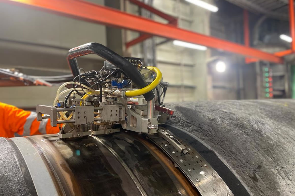
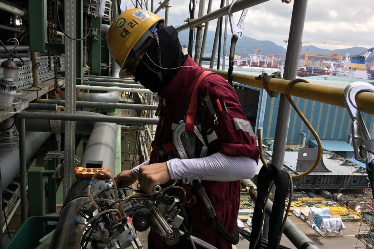
The Conventional PipeWIZARD system, using multiple transducers in pulse-echo or tandem modes, has been modified by R/D Tech to produce a phased-array version called the PipeWIZARD Phased Array. PipeWIZARD-PA stands for: Pipe Weld Inspection using Zone discrimination And Real-time Display with Phased Array.
PipeWIZARD-PA is a automated ultrasonic inspection system for girth welds, primarily for gas and
oil pipelines from 4” up to 60” diameters and from a few up to 50mm and more in wall thickness.
The objective of AUT is to be able to mount the inspection head, inspect the weld, interpret the data, mark the defects, remove the inspection head, save the results on two separate media, and move to the next weld in a matter of minutes (offshore and onshore pipelines).
Phased arrays, unlike conventional ultrasonics, generate and receive ultrasounds electronically. An array of elements, each connected to a separate pulser and time delay generator, is pulsed using a focal law. This focal law defines which elements are to be pulsed and with what time delay. By adjusting the time delays, it is possible to generate normal beams, angled beams, focused or unfocused beams, shear waves or longitudinal waves, depending on the array, wedge, and other parameters.
Electronic scanning, whether linear, sectorial, or DDF, is considerably faster than mechanical scanning. This gives phased arrays a major advantage in speed, as well as reliability. Beam steering offers possibilities that conventional ultrasonics cannot match in cases such as weld and/or complex component inspections. Arrays can be small, which is an advantage where a small footprint is required.
Zone discrimination is an inspection technique used with PipeWIZARD that divides the weld into a series of well-defined, discrete zones, each inspected by its own focused transducer or focal laws if using phased array probes.
The methodology is in compliance with with DNVGL-ST-F101 and ASTM E1961.
Phased Array Ultrasonic Testing (PAUT)
Phased array inspections are done using a probe with multiple elements that can be individually activated. By applying appropriate delays, Phased Array is capable of generating an ultrasonic beam, modelling it according to the desired characteristics of: aperture, angle and focus (electronic beam formation). The focal law may also be dynamically modified between pulses, thereby allowing effective movement of the scan beam (electronic scanning).
An angled beam is achieved by applying a constant pulse time-delay to consecutive Array elements (linear focal law).
Focusing is obtained by adjusting the pulse time-delays of the elements in order to achieve a parabola-shaped sequence, symmetrical to the emitting Array (quadratic focal law). This allows the Phased Array to generate a focused beam at any depth (within a near field)
The resulting data can be combined to form a visual image representing a slice through the part being inspected. Data acquired by the Phased Array during scanning can be video displayed in real time in all conventional formats used by digital instruments: A-scan, B-scan, C-scan and D-scan.
Time of Flight Diffraction (TOFD)
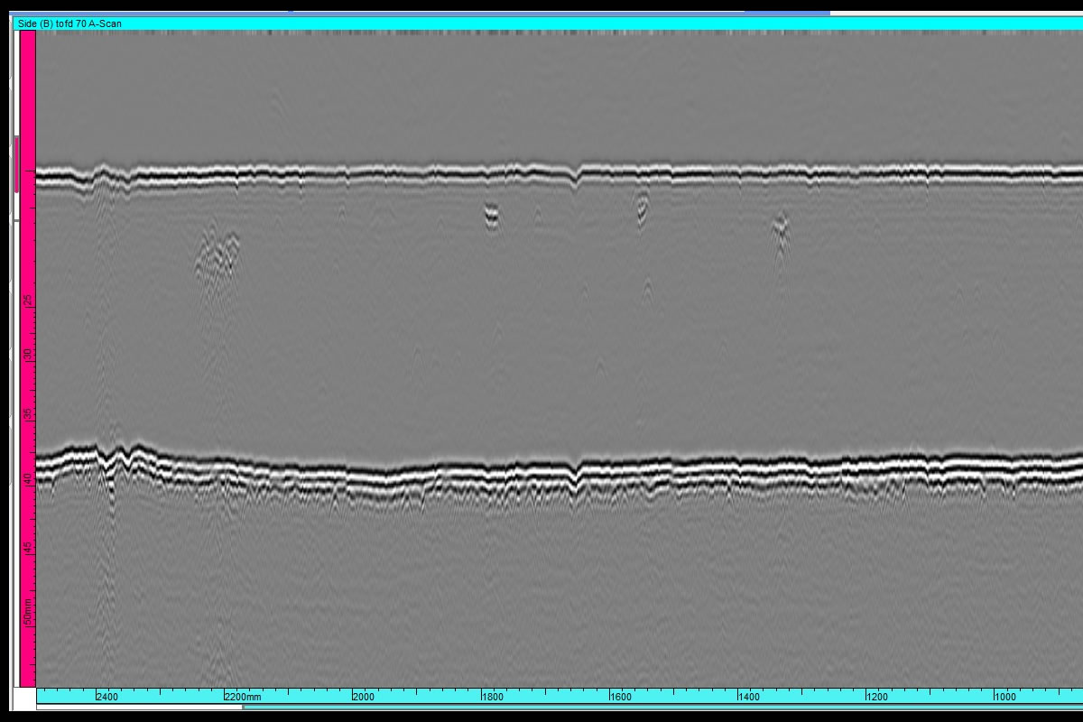
The TOFD (Time of Flight Diffraction) technique is based on the phenomenon of wave diffraction and measures the flight time of waves diffracted from the tips of a discontinuity (defect). TOFD uses two transducers located on opposite sides of a weld with the transducers set at a specified distance from each other. One transducer transmits sound waves and the other transducer acting as a receiver
the same speed as longitudinal waves. Simultaneously, the wavefront that reaches the back wall is partially reflected in a longitudinal and shear component. The longitudinal waves reflected
from the back produce a strong Back-Wall (BW) signal.
Whenever an incident wave beam strikes a defect its surface generates a reflected wave, while its tips act as new point sources of spherical low amplitude waves that propagate in all directions (diffracted waves). By amplifying and running these signals through a computer, defect size and location can be determined with much greater accuracy than by conventional UT methods.
Ultrasonic Testing (UT)
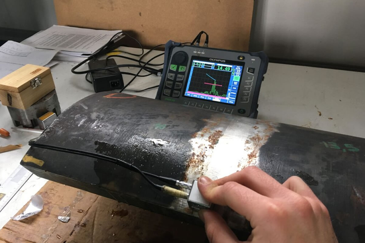
High frequency sound is introduced into the part being inspected and if the sound hits a material with a different acoustic impedance (material density and acoustic velocity), some of the sound will reflect back to the sending unit and can be presented on a visual display. By knowing the speed of the sound in the part and the time required for the sound to return to the sending unit, the distance to the reflector can be calculated.
The two most common types of sound waves used in industrial application are compression (longitudinal) waves and shear (transverse) waves. Shear waves travel at approximately half the speed of longitudinal waves.
Sound is introduced into the part using an ultrasonic transducer (“probe”) that converts electrical pulses into mechanical waves, then converts returning sound back into electric impulses. This signal can be displayed as a visual representation on a digital or LCD screen. The distance from the transducer to the reflector can be determined. The signal can also be interpreted by operators to determine the type of discontinuity (lack of fusions, slag, lack of root penetration, missed edge, porosity, cracks, segregations). Because ultrasound will not travel through air a “couplant” is used between the face of the transducer and the surface of the part to allow the sound to propagate into the part.
Internal Rotating Inspection System (IRIS)
IRIS is an ultrasonic technique applied for the inspection of the remaining wall thickness of tubes. It is more accurate than other tubes inspections and returns information on geometry of the defect and remaining wall thickness. It is often used in conjunction with Eddy Current or Remote Field Testing.
Electromagnetic Testing*
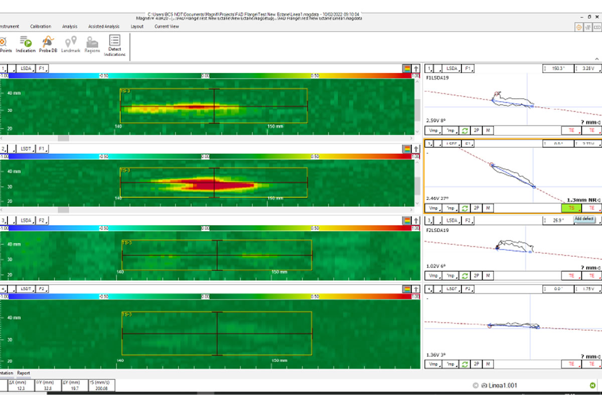
Electromagnetic testing is a general test category that includes Eddy Current testing, Alternating Current Field Measurement (ACFM) and Remote Field testing. All of these techniques use the induction of an electric current or magnetic field into a conductive part, then the resulting effects are recorded and evaluated.
Basic principle: when a coil is excited with an alternating electrical current, it produces a magnetic field around itself. This magnetic field oscillates at the same frequency as the current running through the coil. If the coil approaches a conductive material, currents are induced in the material.
Eddy current makes use of array probes (ECA) to improve versatility of inspection and coverage area. Typical use of Eddy Current is: inspection of heat exchangers, CRA surfaces, tubing, welds.
Advantages:
- Minimal surface preparation required;
- Can detect surface breaking and sub-surface flaws;
- There is no need for couplant or direct contact;
- Can replace standard surface methods;
- Fast inspection;
- Recordable with encoder and stored digitally.
Magnetic Flux Leakage (MFL)
Magnetic Flux Leakage detects anomalies in normal flux patterns created by discontinuities in ferromagnetic material saturated by a magnetic field. This technique can be used for piping and tubing inspection, tank floor inspection and other applications.
Advantages:
- used on all ferromagnetic materials;
- used to inspect finned tubes;
- fast inspection.
Remote Field Testing (RFT)
A magnetic field is created by one coil and is received by a second coil after travelling though the material. This technique allows for detection of internal and external flaws, although it’s not possible to distinguish between them.
Advantages:
- used on ferromagnetic materials;
- detection of internal and external flaws;
- detection of wall loss
Radiographic Inspection (RT)
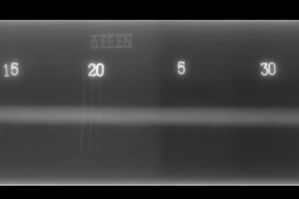
Industrial radiography involves exposing a test object to penetrating radiation so that the radiation passes through the object being inspected and a recording medium placed against the opposite side of that object.
X-rays are generally used for less dense material (i.e. aluminium), or for small wall thicknesses. For thicker material or more dense materials, gamma-ray are used.
The recording media can be industrial x-ray film or a digital radiation detector. The radiation passing through the test object exposes the media, causing an end effect of having darker areas where more radiation has passed through the part and lighter areas where less radiation has penetrated. If there is a void or defect in the part, more radiation passes through, causing a darker image on the film or detector.
Films are used in conventional film radiography, while detectors are used in computed and digital radiography.
Magnetic Particle Testing (MPI)
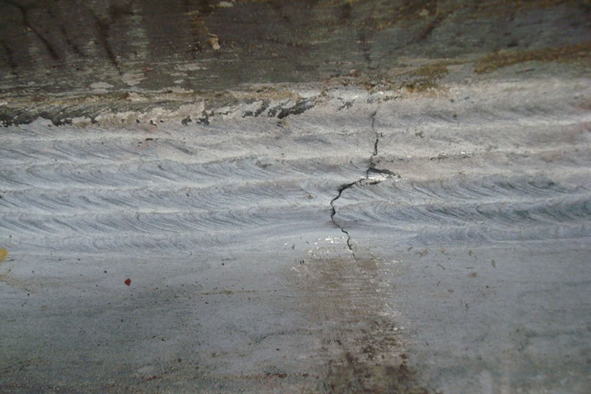
Magnetic Particle Testing is applied to detect surface and near-surface discontinuities in ferromagnetic materials. The sensitivity is higher for surface discontinuities and decreases rapidly with depth. Typical flaws that can be detected with MPI are cracks, lack of fusions, cold laps, laminations.
The magnetic field can be generated with permanent magnets (Direct Current, DC), which penetrates deeper in the part, or electromagnets (Alternating Current, AC).
Either dry or wet magnetic powders may be used for magnetic particle testing and they may be colored with a visible dye (Color Contrast method) or a fluorescent dye (Fluorescent method).
Magnetization techniques are generally one of the following: prods, longitudinal magnetization, circular magnetization, yokes, multidirectional magnetization.
Temperature range limitations are set by the manufacturer.
Liquid Penetrant Testing (PT)
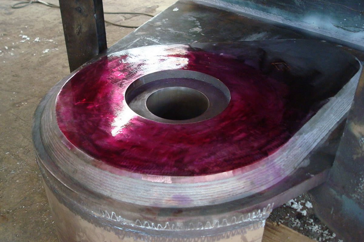
Liquid penetrant testing is a method used to detect discontinuities open to the surface of nonporous materials. Typical flaws detected with PT are cracks, lack of fusions, cold laps, laminations and porosities.
The dyes can be either visible under white light (Color Contrast) or visible under ultraviolet light (Fluorescent). Either of them can be used with one of the following techniques: water washable, post-emulsifying, solvent removable.
The standard technique is applied between 5°C and 52°C temperature. The method might be used with temperatures outside this range, but the procedure has to be qualified according to the specific reference code.
Visual Testing (VT)
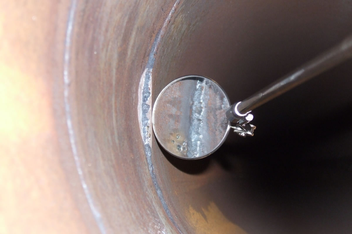
Visual examination is generally used to determine surface condition of the part under test, shape or dimensions of parts, misalignments, corrosion or evidence of leaking. The visual examination is inherent in most other methods, as a visual inspection is often made prior to, or as part of another non destructive test.
Acoustic Emission (AE)*
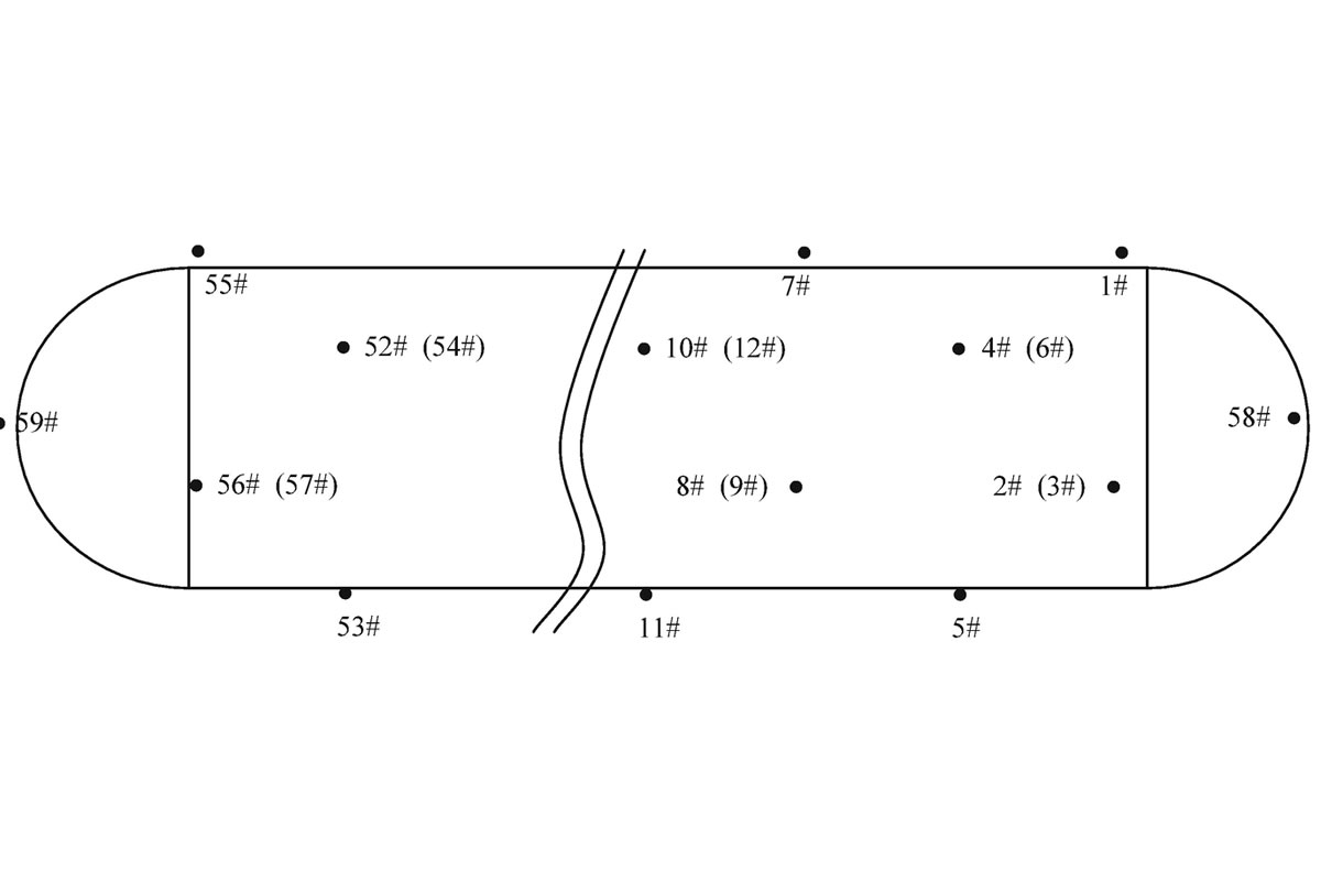
Acoustic Emission Testing is performed by applying sensors on the component to be tested. These sensors are capable of converting a mechanical signal into electrical signals, which are processed by an acquisition unit. These elastic waves are captured when the component is subjected to external force, such as pressure, load or temperature. By using multiple sensors, the acoustic emission sources (discontinuities) can be detected and located in the part.
The method is capable to locate damages and differentiate them based on the signal response. Nevertheless, further inspection is generally required for a full assessment of the damage.
As a limitation, the method cannot detect flaws that do not move or grow.
*Activity not under ACCREDIA accreditation.
